AMX Mouse: Difference between revisions
m (→PCB layout) |
No edit summary |
||
| Line 8: | Line 8: | ||
Add details about AMX Pagemaker and other apps here. | Add details about AMX Pagemaker and other apps here. | ||
== Ports == | |||
Port mapping is via A5, A6 and A7. | |||
These are decoded by the button reader ( Port 223 or 0xDF ) and directly by the z80 PIO chip, which responds to any combination of these address lines while a7 is low. This is because of the following mapping. | |||
A5=A/!B select. | |||
A6=D/!C select. | |||
A7=Chip Enable. | |||
This results in four useable ports for the z80 PIO - | |||
Port 31 ( 0x1F ) | |||
Port 63 ( 0x3F ) | |||
Port 91 ( 0x5F ) | |||
Port 127 ( 0x7F ) | |||
Also, the button decode is performed through direct I/O and pulling the relevant data line low. The button port is | |||
Port 223 ( 0xDF ) | |||
Reading from this port will result in reading the mouse buttons. | |||
LMB - Bit 7 low when pressed. | |||
MMB - Bit 6 low when pressed. | |||
RMB - Bit 5 low when pressed. | |||
== Circuit Layout == | == Circuit Layout == | ||
Revision as of 03:31, 9 October 2022
The AMX Mouse comprises a bus-mouse and edge-connector interface created by Advanced Memory Systems.
It provided a 20 pin TTL bus-mouse interface and a 26 pin (25 pin, as it went to a DB25 via ribbon cable) Centronics style parallel port that supported the Strobe and Busy lines along with 8 data bits.
(Photo to go here.)
Software
Add details about AMX Pagemaker and other apps here.
Ports
Port mapping is via A5, A6 and A7.
These are decoded by the button reader ( Port 223 or 0xDF ) and directly by the z80 PIO chip, which responds to any combination of these address lines while a7 is low. This is because of the following mapping.
A5=A/!B select. A6=D/!C select. A7=Chip Enable.
This results in four useable ports for the z80 PIO -
Port 31 ( 0x1F ) Port 63 ( 0x3F ) Port 91 ( 0x5F ) Port 127 ( 0x7F )
Also, the button decode is performed through direct I/O and pulling the relevant data line low. The button port is
Port 223 ( 0xDF )
Reading from this port will result in reading the mouse buttons.
LMB - Bit 7 low when pressed. MMB - Bit 6 low when pressed. RMB - Bit 5 low when pressed.
Circuit Layout
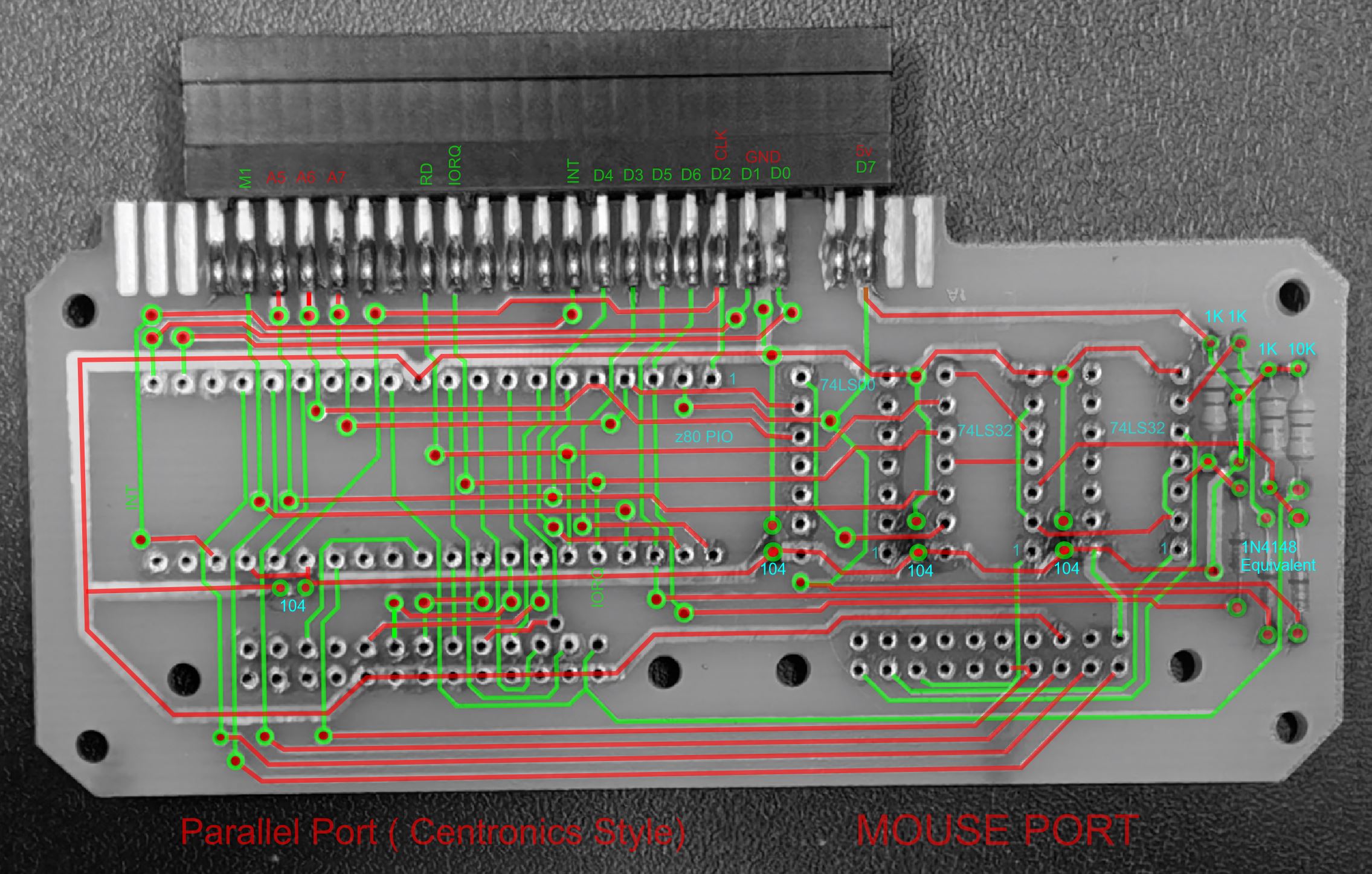
PCB layout
PCB layout is a relatively simple double-layer PCB that sits flat behind the ZX Edge connector.
The four resistors are all 1K for the button pullups and 10K for the Strobe pullup. The diodes are small signal diodes, likely 1N4148
Decoding uses A5, A6 and A7, and decoding for the z80 PIO is performed by the PIO itself as it has a chip enable and IORQ pin, however despite free inputs on the PIO, the Mouse Buttons are decoded separately and their output put onto the data lines via the diodes. Four decoupling capacitors ( 0.1uF or "104" ) noted next to each IC.
External links
Add in external links here.
